Definition of Impedance Control
1. Overview
When we want to design how much resistance (weight, spring-like feeling) a human feels from a robot arm or a rehabilitation robot,
one of the most common strategies is impedance control.
The basic idea of impedance control is simple:
“When a person pushes a joint, the joint should respond like a virtual mass–damper–spring system.”
Therefore, regardless of the robot’s real inertia, friction, or gravity,
the human should feel the motion as if it were governed by the parameters $I_d, b_d, k_d$ that we choose.
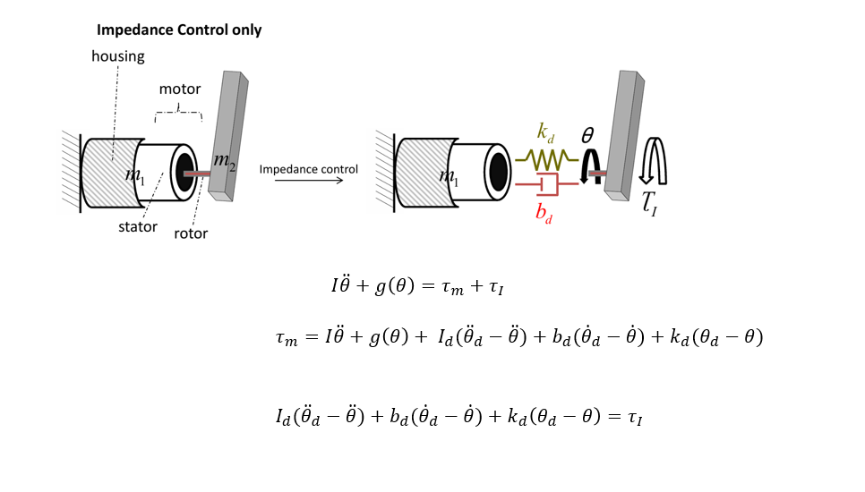
Think of a motor-driven joint where a person applies torque, as in the figure above.
2. Joint Dynamics Model
First, the actual joint dynamics can be written as
\[I\ddot\theta + g(\theta) = \tau_m + \tau_I\](1)
- $I$: actual joint inertia (moment of inertia)
- $\theta$: joint angle
- $g(\theta)$: torque due to gravity (gravity term)
- $\tau_m$: control torque applied to the joint by the motor/controller
- $\tau_I$: external/interaction torque applied to the joint by the human (or the environment)
In other words, the sum of the motor torque and the human torque produces the inertia + gravity terms in (1).
3. Structure of the Impedance Controller
In impedance control, we specify a virtual mass–damper–spring that the human should feel:
- desired mass: $I_d$
- desired damping: $b_d$
- desired stiffness: $k_d$
- desired trajectory (position, velocity, acceleration): $\theta_d, \dot\theta_d, \ddot\theta_d$
We assume the controller generates the motor torque as
\[\tau_m = I\ddot\theta + g(\theta) + I_d(\ddot\theta_d - \ddot\theta) + b_d(\dot\theta_d - \dot\theta) + k_d(\theta_d - \theta)\](2)
The first term, $I\ddot\theta + g(\theta)$, compensates the real inertia and gravity,
and the remaining three terms implement the virtual mass–damper–spring behavior.
4. Deriving the Force–Displacement Relation
Now substitute (2) into the joint dynamics (1).
Plugging (2) into (1) gives
\[I\ddot\theta + g(\theta) = \Big[ I\ddot\theta + g(\theta) + I_d(\ddot\theta_d - \ddot\theta) + b_d(\dot\theta_d - \dot\theta) + k_d(\theta_d - \theta) \Big] + \tau_I\]Canceling $I\ddot\theta + g(\theta)$ from both sides,
\[I_d(\ddot\theta_d - \ddot\theta) + b_d(\dot\theta_d - \dot\theta) + k_d(\theta_d - \theta) = -\,\tau_I\]If we change the sign convention (or move terms to the other side), we usually write
\[I_d(\ddot\theta_d - \ddot\theta) + b_d(\dot\theta_d - \dot\theta) + k_d(\theta_d - \theta) = \tau_I\](3)
This is the core equation of impedance control.
The external torque $\tau_I$ applied by the human
is made proportional to the error of a “virtual mass–damper–spring” system $(I_d, b_d, k_d)$
by appropriately choosing the motor torque $\tau_m$.
From the human’s point of view, the joint behaves as if it had
mass $I_d$, damping $b_d$, and stiffness $k_d$ around the desired trajectory $\theta_d$.
5. Summary
- $\tau_m$: control torque applied to the joint by the motor
- $\tau_I$: external torque applied to the joint by the human (or the environment)
- Impedance control compensates the real inertia and gravity of the robot and
designs virtual mass–damper–spring parameters $I_d, b_d, k_d$ that the human will feel. - The final goal is to make the relationship between human torque $\tau_I$ and joint motion error $(\theta_d - \theta)$
satisfy a linear impedance relation like (3).
With this formulation, we can later explain rehabilitation robot experiments in terms of
which impedance values were applied to, for example, the shoulder joint,
and how we designed the perceived stiffness and damping that the participant would feel.